
Solutions
 Breadcrumb: Home > Solutions > Speed Measurement
 Updated:2026-11-02
 Views:
In motor test benches, multi-station production lines and multi-axis machinery, engineers often need rotational speed from several measurement points at the same instant. The usual practice is one single-channel tachometer per point: wiring multiplies, the meters do not share a time base, and the speed differences have to be aligned by hand afterwards. This article describes the composition and functions of the LUYOR-904 four-channel speed acquisition system - four channels sampled together, four-color live curves on one screen, independent alarm limits and pulses-per-revolution settings for each channel, and logging with CSV, Excel and report export - and lists the technical specifications and wiring points that matter in commissioning.
In motor test bench trials, multi-station production line inspection and condition monitoring of multi-axis machinery, it is often necessary to acquire the rotational speed of several measurement points at the same moment and compare them. The traditional approach is to measure separately with several single-channel tachometers: more equipment, tangled wiring, no common time base across meters, and manual time alignment afterwards when comparing speed differences.
Now a single LUYOR-904 acquisition module can accept 4 LUYOR ROLS-5PW laser speed sensors at the same time. With the host software, the LUYOR-ROLS-5PW four-channel speed acquisition system, it provides four-channel synchronous acquisition, four-color curve comparison, an independent alarm per channel and one-click report export - one system doing the work of four single-channel tachometers.
| Measurement points 1-4 | 4 × LUYOR ROLS-5PW laser speed sensors, non-contact measurement, reflective patch or tape on the shaft end, one (or more) pulse per revolution |
| Acquisition module | LUYOR-904 (5DI/4DI digital input module), USB powered, CH340C virtual serial port, standard Modbus-RTU protocol |
| Host software | Four-channel speed acquisition system, single Windows executable, no installation and no programming required |
DI0-DI3 on the module correspond to channels 1-4 in the software interface. One polling cycle needs just 3 commands to read back all channel data, so the four measurement points share an identical time base: speed differences and synchronization can be compared directly, without the misalignment that occurs between separate meters.
The four channels are plotted together in purple, blue, green and orange, with current values in the legend at the upper right. The curves are refreshed by a dedicated timer at about 8 times per second and scroll smoothly. The displayed quantity can be switched between rotational speed (rpm) and frequency (Hz) with one click, and the time window on the horizontal axis is adjustable. Numeric readouts refresh at the set interval and are smoothed, so they stay steady instead of jumping.
Upper and lower speed limits are set separately for each of the four channels. When any channel exceeds a limit, its card flashes red, the corresponding segment of the curve turns red at the same time, the log row is shown in red text, and the status bar names the channel (for example, "channel 4 above upper limit"), so the faulting channel and the time window can be identified at a glance.
Each channel has its own pulses-per-revolution setting: 1 for a single reflective patch, 60 for a 60-tooth gear, 1000 for a 1000-line encoder. Speed = frequency (Hz) × 60 ÷ pulses per revolution, and the four channels do not affect each other.
Clicking Start logging records to the "Records" folder in the program directory as it samples, so an unexpected power loss or program error does not lose data that has already been logged. Log timestamps are accurate to the millisecond. Data can be exported as CSV, Excel (rows beyond the alarm limits are automatically shown in bold red) and a TXT statistical report - the report gives average, upper limit, lower limit, speed fluctuation and standard deviation per channel by section, plus the earliest 200 sampling points, ready for use in a test report.
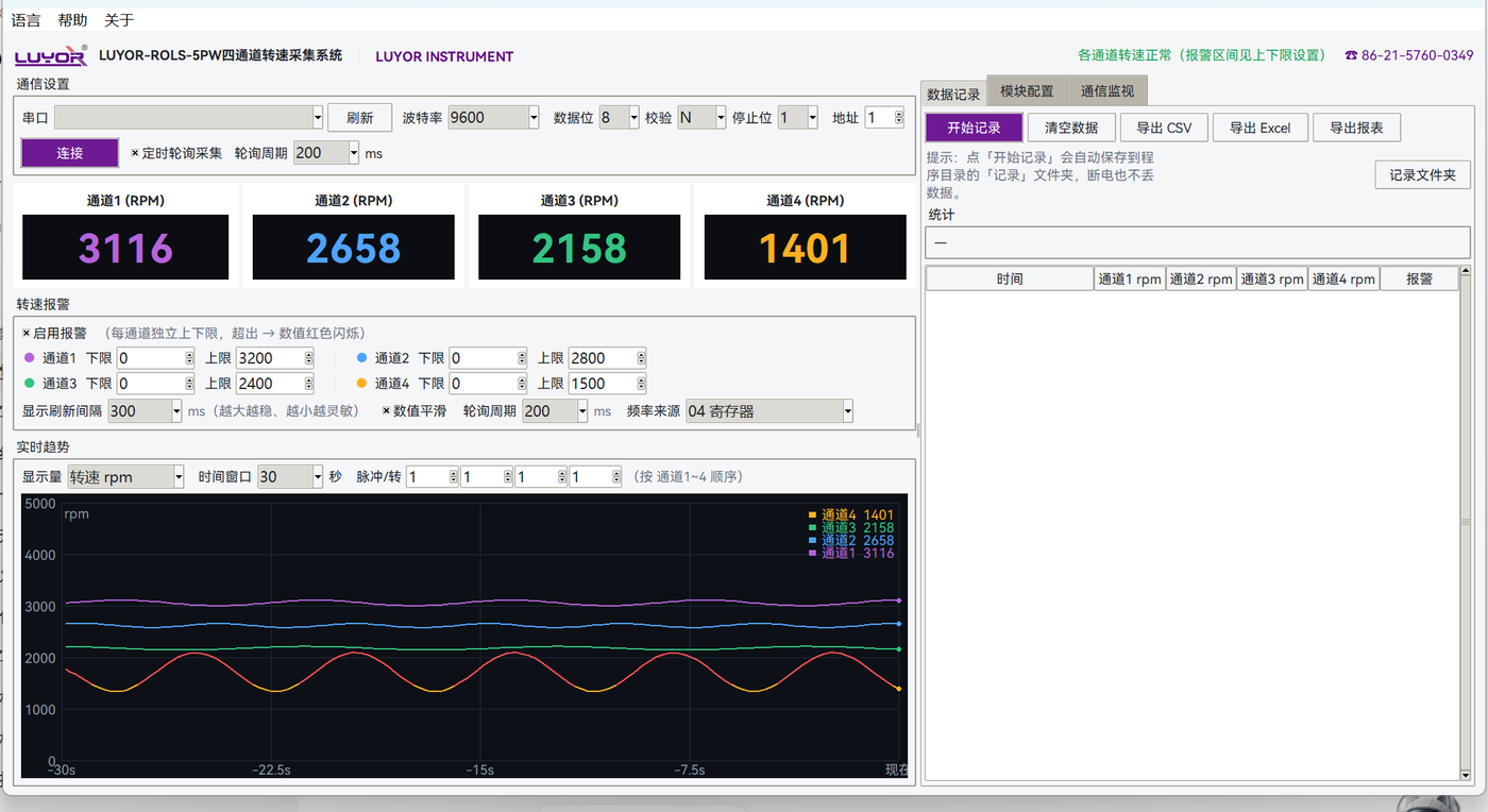
Software main screen: four-channel LED speed cards and four-color live curves (channel 4 is above its upper limit in this example, and that segment of its curve is shown in red)
| Acquisition channels | 4 (DI0-DI3 ↔ channels 1-4) |
| Input speed rating | DI0 / DI1 high-speed inputs, 50 kHz maximum; DI2 / DI3, 2 kHz maximum |
| Polling period | 200 ms by default; all channels are read back in each cycle |
| Curve refresh | About 8 times per second (independent of the numeric refresh) |
| Sampling rate settings | 100 Hz / 200 Hz / 500 Hz / 1 kHz / 2 kHz / 3 kHz, with automatic selection based on the measured frequency |
| Communication | Modbus-RTU, default 9600 bps, n,8,1, address 01 |
| Data export | CSV / Excel (out-of-limit rows in bold red) / TXT statistical report |
| Operating environment | Windows desktop (portable exe); the interface can switch between Simplified Chinese and English at runtime |
Connect the negative leads of the 4 laser speed sensors to the module GND (black wire), and the signal wires to DI0-DI3 respectively.
Channel 1 and channel 2 correspond to DI0 and DI1 (high-speed inputs, 50 kHz maximum), so route the highest-speed measurement points to these two channels; channel 3 and channel 4 correspond to DI2 and DI3 (2 kHz maximum).
NPN sensors are supported by default; if you use PNP sensors, change the input type to PNP on the Module configuration page in the software and write the setting.
Connect the sensor positive lead to the positive supply rail, or use the 5V/100mA output on the module to power the sensors.
Speed comparison across several measurement points on motors, fans, pumps, gearboxes and other rotating equipment.
Bench testing: measuring the input shaft, output shaft and intermediate shaft of the same machine together to evaluate transmission ratio and efficiency.
Spot checks and long continuous records at multiple stations on a production line.
Condition monitoring: automatic alarms on abnormal speed with logged records for traceability and analysis.
For an on-site demonstration, a trial unit or help with selection, contact LUYOR INSTRUMENT: Tel 86-21-5760-0349.
This article belongs to the speed and stroboscopic measurement section.
Other sections on the same product line include speed sensors (wired to a PLC or a DAQ card for continuous monitoring, outputting an electrical signal) and industrial test instruments (the entry point for UV inspection, speed measurement, stroboscopic observation and surface inspection).
Ranges, accuracy and accessory lists for each model are listed on the product pages.

Email: info@xinysun.com

Tel: 131-2093-6518

Address: 1525 Minqiang Road, Bldg 26, Songjiang, Shanghai

Copyright 2026 Xinysun Instrument (Shanghai) Co., Ltd. All rights reserved.
ICP:ICP-2026046447




 Industrial Test Instruments


