
Products
PRODUCTS Breadcrumb: Home > Products > Industrial Test Instruments > Tachometer Sensors
 Overview
SPLS-5PW is a laser tachometer set pairing a ROLS-5PW sensor with a power module: 1-300,000 rpm, 7 m distance, 0-5 V TTL BNC output and 60 h battery.
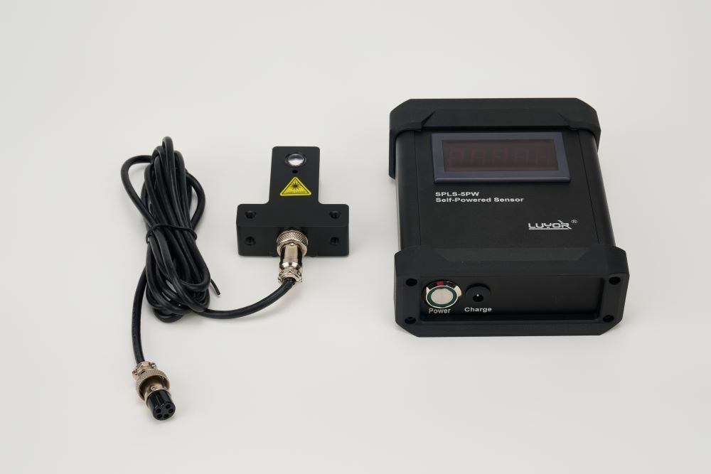
Many customers see the model number and assume that SPLS-5PW is a single probe. In fact it is a set built from two parts:
Built-in rechargeable lithium battery supplies the sensor
Conditions the pulse signal to 0-5 V TTL and outputs it through a BNC connector
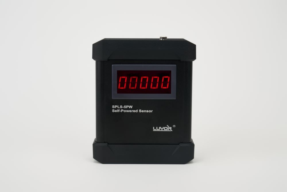
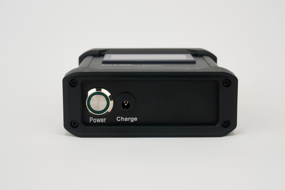
Housing carries a speed display, a power switch, and a charging jack
Built-in reverse-polarity and voltage-regulation protection circuits
650 nm frequency-modulated laser, non-contact speed measurement, range 1-300,000 rpm
Measurement distance up to 7 m, with a built-in high-frequency filter that rejects ambient light
Weight 38 g, L-bracket included, signal LED on the rear
The same probe as our laser tachometer sensor ROLS-5PW
So what arrives is an aluminum carry case holding the module, the sensor, reflective tape, the bracket, and a BNC cable. No separate power supply or display meter is needed; measurement starts out of the box.
The standard sensor (ROLS-5PW) meets the same class of problem on many sites. SPLS-5PW is built for exactly these cases:
The sensor needs an external 5 V DC supply. At temporary monitoring points, on elevated equipment, or on a mobile test rig, running a 5 V line often takes more effort than the measurement itself.
Vibration analyzers, spectrum analyzers, data recorders, and stroboscopes almost all use BNC coaxial sockets for external trigger input. The standard sensor ends in three tinned bare wires, which will not mate with them.
When you align the beam or walk a route, you need to see the speed on the spot to confirm the signal is captured. A pulse line on its own is not enough.
All three lead to the same answer: a speed probe that carries its own supply, outputs BNC directly, and includes a display. That is SPLS-5PW.
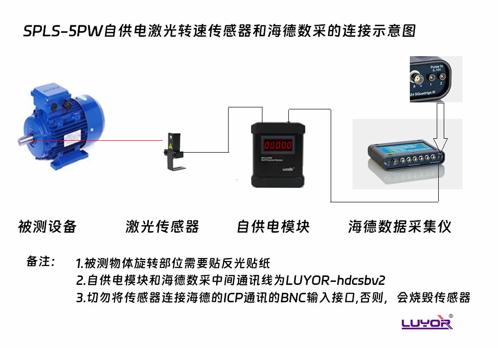
The official positioning is stated plainly. It is the component that delivers one pulse per revolution to these instruments:
The same signal also covers stroboscope external trigger, waveform analyzers, and tape recorders. In vibration work this line is called the keyphasor signal. Its job is not to show a speed number but to give every vibration sample a time reference. Without it, the spectrum smears as soon as speed changes.
| Item | ROLS-5PW (standard) | SPLS-5PW (self-powered, this page) |
|---|---|---|
| Power supply | External 5 V DC required | Built-in 4.2 V/5000 mAh lithium battery; 115/230 V AC supply also possible |
| Output connector | Three-core tinned bare wire, brown/blue/black | BNC coaxial connector, 0-5 V TTL compatible pulse |
| Display | None; a panel meter or DAQ is needed | Speed display on the module (99999 RPM) |
| Continuous run time | Depends on the external supply | About 60 h on a full charge; continuous operation on AC |
| Cable supplied | 2.4 m three-core tinned shielded cable | 2.4 m cable plus BNC cable |
| Reflective tape | T5 reflective tape | 6 m reflective tape |
| Mounting | L-bracket (standard), magnetic base (optional) | L-bracket and two nuts (standard) |
| Suited to | Fixed installation near a control cabinet, long-term online monitoring | Portable routes, temporary points, BNC direct to instruments |
The module travels in the carry case. At the point you take it out, fit the bracket, apply the reflective tape, switch on, and measure. It works as a two-piece portable laser tachometer while keeping the BNC output. What it adds over a handheld meter is the ability to feed the signal to an analyzer.
Fault diagnosis, modal tests, and trial runs often last just a few days. Pulling in a power line is not economical, and one battery in SPLS-5PW runs about 60 h continuously. That removes the wiring step and speeds up deployment considerably.
For long-term monitoring, power the module from 115/230 V AC and battery capacity no longer limits the run. It then behaves like the standard sensor, delivering pulses from a fixed point over the long term.
| Item | Value | Notes |
|---|---|---|
| Battery | 4.2 V/5000 mAh rechargeable lithium | The official text writes 5,000mHA, a unit typo; 4.2 V is the charge cutoff voltage of a lithium cell, with nominal voltage about 3.7 V |
| Continuous run time | About 60 h (full charge) | Official English specification and product page; some Chinese documents state about 100 h, and both figures circulate, so the manual supplied with the unit takes precedence |
| Charging time | About 5-8 h | With the dedicated charger; charging jack on the housing |
| AC supply | 115/230 V AC | Some Chinese documents state 110-260 V AC, a wide-range wording |
| Output signal | 0-5 V TTL compatible pulse | Pulse width depends on target size and speed |
| Module display range | 99999 RPM | The display limit is below the 300,000 rpm sensor range; at very high speed, read the downstream instrument |
In addition to the ROLS-5PW supplied as standard, the SPLS-IM module can be used with the tachometer sensors listed below (sensors ordered separately):
| Compatible sensor | Brand | Part number | Notes |
|---|---|---|---|
| ROLS-5PW | LUYOR, USA | — | Supplied as standard with SPLS-5PW, 650 nm laser, 7 m, 1-300,000 rpm |
In other words, buy the module once and select the sensor to match the point. Changing the measuring point or the light source later does not mean buying the whole set again. If the downstream instrument itself recognizes a positive pulse, either sensor works.
Power and signal-output module with speed display (SPLS-IM)
ROLS-5PW laser tachometer sensor
2.4 m cable
BNC cable
6 m reflective tape
L-shaped mounting bracket and two nuts
Charger
User manual, certificate of conformity, warranty card
Aluminum carry case (storage and transport)
Factory inspection documents
Portable measurement is one of the main ways this set is used. If the module, sensor, bracket, tape, and cables were loose, parts would be lost on site and the sensor lens would be knocked.
A rigid aluminum case holds the set in fixed positions, so it comes out ready and goes back packed, and it travels easily between workshops and plants. For technicians who visit sites regularly, that point is more concrete than a figure on a data sheet.
Fix the sensor to a frame or surface near the machine with the L-bracket. Mount it on the bracket, not on the measured object. The module can sit within reach or inside the case; switch on and read, with no extra supply or meter head. Where vibration is high, use a rigid bracket so the optical path does not shift over time.
Place reflective tape on a rotating surface that the laser reaches steadily. Press it down flat with no lifted edges. If the surface itself is strongly reflective (polished shaft, chrome plating, oil film), press matte tape over it to hold down the background before applying the reflective tape.
Adjust the bracket so the beam strikes the tape as close to perpendicular as possible. This step needs no external instrument. Watch the blue signal LED on the rear of the sensor: it flashes on each reflected pulse and appears steady as speed rises. At the same time, check that the module display shows a number; when both behave correctly, the optical path is aligned.
Run the supplied BNC cable to the speed input of the analyzer or DAQ and confirm that the instrument recognizes pulses. Before routine use, compare against a machine with a known speed and confirm that the readings agree.
SPLS-5PW is the version in this series with its own battery, a BNC output, and a speed display. The other four are bare sensors that differ in supply voltage and cable length:
| Model | Supply | Cable | Output | How to choose |
|---|---|---|---|---|
| ROLS-5PW | 5 V | 2.4 m | Three-core tinned bare wire | For a LUYOR-910 panel meter or 5 V DAQ supply, with the point near the control cabinet |
| ROLS-5PW-25 | 5 V | 7.6 m | Three-core tinned bare wire | As above, with the point farther from the control cabinet |
| ROLS24-5PW | 24 V | 2.4 m | Three-core tinned bare wire | The site already has a 24 V control system, so power is drawn directly and the step-down module is not needed |
| ROLS24-5PW-25 | 24 V | 7.6 m | Three-core tinned bare wire | 24 V system with a longer installation distance |
| SPLS-5PW | Built-in lithium battery/115-230 V AC | 2.4 m (custom lengths available) | BNC, 0-5 V TTL | Portable routes, temporary points, BNC back end, reading while measuring |
The point is fixed and 5 V or 24 V power is already available nearby
The back end is a terminal-block panel meter or a PLC input module, where bare wire connects more easily
A display meter already exists, so the module does not need one
The point runs online long term without movement, where the standard version is more economical
Signal cable can be made to 7.6 m, 15 m, 30 m, or 60 m, and runs up to 100 m with shielded cable.
Any extension must use shielded cable with a reliable ground. Otherwise electromagnetic interference picked up over the long run contaminates the pulse signal and shows up as jumping speed readings.
The data is split into the power module and the laser sensor. The figures below come from official specification documents and can be used directly for selection and internal approval:
| Output signal | TTL compatible pulse, 0-5 V (pulse width depends on target size and speed) |
| Output connector | BNC coaxial connector |
| Display | Speed reading on the module, display range 99999 RPM |
| Measurement range | Matches the sensor fitted (1-300,000 rpm with ROLS-5PW) |
| Rechargeable battery | 4.2 V/5000 mAh rechargeable lithium |
| Continuous run time | About 60 h on a full charge (official English figure; Chinese documents also state about 100 h) |
| Charging time | About 5-8 h |
| AC supply | 115/230 V AC (one document states 110-260 V AC) |
| Controls on the housing | Power switch, charging jack |
| Protection | Built-in reverse-polarity and voltage-regulation protection |
| Output signal | Pulse output |
| Measurement range | 1-300,000 rpm (1-5,000 Hz) |
| Measurement distance | Up to 7 m (official recommendation is within 7.6 m) |
| Supply voltage | 5 V DC (provided by the SPLS-IM module) |
| Operating current | Less than 30 mA |
| Laser | 650 nm frequency-modulated laser; output power below 2 mW; Class 2 laser |
| Interference rejection | Built-in high-frequency filter, unaffected by ambient light |
| Optics | Large-diameter collector lens receives weak return signals |
| Protection | Short-circuit protection, reverse-voltage protection, over-voltage protection 15 V/1 minute |
| Operating temperature | -10 to 50 ℃ |
| Storage temperature | -40 to 85 ℃ |
| Ingress protection | IP60 (digit 6 = dust-tight; digit 0 = no water protection) |
| Shock rating | IEC 60028-27 |
| Housing material | Nylon (Nylamid) |
| Weight | 38 g |
| Signal LED | On the rear of the housing, flashes once per received pulse; allows beam alignment without a meter |
| Mounting | L-bracket and two nuts (standard) |
The sensor is not water-resistant: IP60 addresses dust protection alone. Do not wash or hose the surface; wipe it with a cloth
Shelter it outdoors: outdoor operation requires a rain cover or an enclosure (the module must never be exposed to rain)
Lithium battery storage: for long idle periods, store at about half charge and avoid deep discharge; charge with the supplied charger
Extend signal cable with shielded cable and a reliable ground, or interference over the long run causes jumping readings
Do not open the unit: the optics and amplifier need specialist equipment and calibration; return damaged units to an authorized repair station or the LUYOR China service center
Laser life: typically about 5,000-20,000 h; for long-term use, include it in the equipment inspection record
Laser diode: output power below 2 mW, wavelength 650 nm, Class 2 laser.
Do not look into the direct or reflected beam, and do not stare at the spot
Do not aim the laser at anyone's eyes, or at mirrors and other strongly reflective objects that people may look into
Never aim the laser at aircraft or vehicles, which can distract a driver or pilot and is unsafe and illegal
Wear laser safety glasses during installation and alignment, and avoid working with the beam at eye height
It is a complete set, not a single sensor. It has two parts: a power and signal-output module with a speed display (official model SPLS-IM), and an ROLS-5PW laser tachometer sensor. The sensor turns speed into pulses; the module powers the sensor, conditions the signal into 0-5 V TTL pulses at a BNC connector, and shows the speed value. What arrives is an aluminum carry case that works out of the box, with no separate power supply or display meter.
Both use the same ROLS-5PW laser sensor. The difference is power supply and output form. ROLS-5PW is a bare sensor: it needs an external 5 V DC supply, ends in brown/blue/black tinned wires, and has no screen, which suits fixed long-term monitoring near a control cabinet, where power and a panel meter or PLC connection already exist. SPLS-5PW adds a self-powered module with a lithium battery, BNC output, and a speed display, which suits sites without 5 V power or instruments whose inputs are BNC. The decision rule: if power and terminals are already in place and the point runs online long term, take ROLS-5PW; if you need portability, temporary points, or a direct BNC connection to an instrument, take SPLS-5PW.
BNC is the common speed-signal interface in vibration analysis, spectrum analysis, and data acquisition. Typical instruments named in the official documentation include vibration analyzers, spectrum analyzers, stroboscopes, data acquisition units, tachometers, balancers, waveform analyzers, and tape recorders, whose speed or external trigger inputs are almost all BNC sockets. The output is a standard 0-5 V TTL compatible pulse, one pulse per revolution, which is the keyphasor signal used in vibration analysis. If the back end is a terminal-block PLC or panel meter, a BNC-to-terminal adapter is all that is needed, and we can supply the adapter cable.
Two figures do circulate. The official English specification and product page state 60 hours of continuous operation on a full charge; some Chinese documents, distributor pages included, state about 100 hours. We use the official English figure of 60 hours and mark the difference in the specification section. Actual run time also depends on ambient temperature, target reflectivity, speed, and backlight use. The manual supplied with the unit is the reference, and we will update this page once LUYOR confirms the figure in writing. For long continuous use, power the module from 115/230 V AC and the battery is no longer a limit.
The housing has a power switch and a charging jack, and a dedicated charger is included; the official charging time is about 5-8 h. Because it is a lithium battery, charge it as you go and avoid storing it deeply discharged. For long continuous monitoring, power it directly from 115/230 V AC, which is independent of remaining battery capacity. Whether simultaneous charging and operation is supported should be confirmed in the supplied manual, and we can also check with LUYOR for you.
Because the core of vibration analysis is tying vibration to speed. Bearing and gear fault frequencies are integer or fractional multiples of shaft speed, and the software needs a one-pulse-per-revolution speed signal to run order analysis, remove speed fluctuation from the spectrum, and complete the phase reference for balancing. Without this keyphasor signal you are limited to a fixed-frequency spectrum, and the data smears as soon as speed changes. SPLS-5PW supplies that reference signal, self-powered and BNC direct, which makes deployment on site faster.
It shows the live speed value, with a display range of 99999 RPM. That lets you read while measuring, which helps during beam alignment and route checks without connecting a separate meter. Two limits apply: the display limit is below the sensor range, since ROLS-5PW covers 1-300,000 rpm while the module displays to 99999 rpm, so at very high speed read the downstream instrument; and there is no data storage or reporting, so formal records still come from the vibration analyzer or DAQ.
No new set is needed. The module is a general power and signal-output host, and the sensor is selected to suit the point. If you already have LUYOR sensors on hand, check that the model uses a P-type connector and it will usually connect directly.
Both are modules that power a tachometer sensor and output pulses at BNC, sharing the same approach with different emphasis. The SPLS-IM on this page uses a 4.2 V/5000 mAh lithium battery, runs about 60 h, includes a speed display, and accepts 115/230 V AC. For reading while measuring, choose SPLS; the lists of compatible sensors for the two modules are largely the same.
It is required. These sensors work by counting reflected light: the laser strikes the reflective tape and the sensor outputs one pulse per revolution of the target. Tape goes on a rotating surface that the beam reaches steadily, with as little reflection as possible elsewhere in the beam. Polished shafts, chrome plating, and oil films raise the background, so press matte tape over them beforehand. The standard package includes 6 m of reflective tape; it is a consumable, and tape that ages or collects dust should be replaced promptly or readings become unstable or drop out.
It is not waterproof. The ROLS-5PW housing is rated IP60, where the digit 6 means dust-tight and the digit 0 means no water protection. Do not wash or hose a dirty surface, wipe it with a cloth instead; do not install it at a wash-down station or where condensation or water spray is directed at it; and outdoors it must have a rain cover or enclosure. It does contain a high-frequency filter, so strong workshop light or direct sunlight does not affect the signal output, but that is optical interference rejection, not environmental protection, and the two should not be confused.
Xinysun Instruments (Shanghai) stocks LUYOR products and provides local sales and service support. SPLS-5PW is normally held in stock, and the module and sensor can also be ordered separately. We can advise on wiring and connector conversion, on mounting position and beam alignment, and on matching the unit to your vibration analyzer or DAQ. Signal cable can be made to 7.6 m, 15 m, 30 m, or 60 m, and extended to 100 m with shielded cable and a reliable ground. Call 131-2093-6518, or leave the instrument model and operating conditions in the form at the bottom of this page.
SPLS-5PW official specification document and user manual
SPLS-IM module sensor compatibility list and interface notes
BNC-to-terminal and third-party DAQ adapter and cable practice
Stock in Shanghai; module and sensor can be ordered separately
Support with connector conversion, mounting, and beam alignment
Original factory warranty; consumables such as reflective tape and cables supplied long term
Send inquiry

Email: info@xinysun.com

Tel: 131-2093-6518

Address: 1525 Minqiang Road, Bldg 26, Songjiang, Shanghai

Copyright 2026 Xinysun Instrument (Shanghai) Co., Ltd. All rights reserved.
ICP:ICP-2026046447




 Products
 Applications
 Previous:
 Back to list

 Industrial Test Instruments


